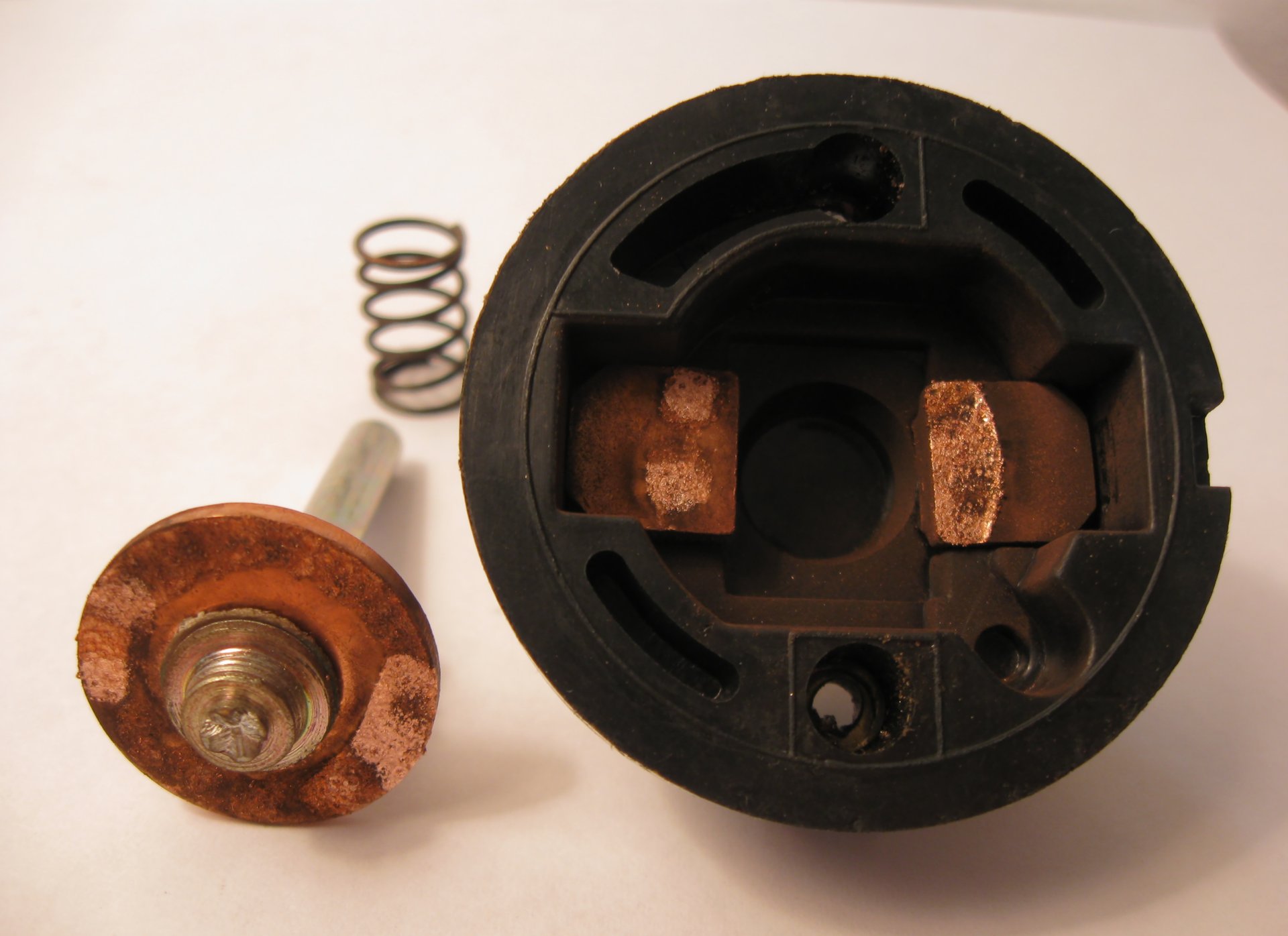

Battery disconnect relays isolate a vehicle or machine battery electrically instead of manually. This article compares monostable and latching control types, load sizing, fail-safe logic and application matching for wholesale and fleet buyers.
Battery disconnect relays isolate a vehicle or machine battery electrically instead of manually. This article compares monostable and latching control types, load sizing, fail-safe logic and application matching for wholesale and fleet buyers.
A truck parked between shifts rarely goes fully to sleep. Clocks, telematics units, control modules and memory circuits keep drawing current, and across a long layoff that small draw can take a battery below the level needed to crank the engine. The traditional fix is a manual master switch mounted on the battery cable. The route more fleets and equipment builders are taking is a battery disconnect relay, which does the same job electrically and adds control options a hand-operated switch cannot offer.
For distributors and fleet buyers, the disconnect relay is also an easy part to mis-specify. The same product may be listed as a battery cutoff relay, a battery master relay or a battery disconnect contactor. These labels overlap, though they do not always describe identical constructions, so the specification sheet matters more than the name on the box. Two relays carrying the same current figure can behave differently the first time the control circuit loses power, or the first time the relay is asked to open under load. The sections below cover control types, load sizing, fail-safe behavior and application matching, ending with what to verify with a supplier before an order is placed.
A manual master switch has three structural limitations. It needs physical access, which is awkward when batteries sit in locked compartments or behind panels on machinery. It forces heavy battery cable to be routed to wherever the operator can reach. And it switches nothing unless someone walks up and turns it.
A remote battery disconnect relay sits directly at the battery and is controlled over a light-gauge signal wire. That removes the cable run to the cab or panel, and it opens up control behavior a mechanical switch cannot match. The relay can be triggered by the ignition circuit, by an alarm or immobilizer, by a timer, or remotely through a telematics system. A fleet can disconnect a parked vehicle from a dispatch screen, or cut power automatically when a vehicle sits unused past a set threshold.
For where the disconnect relay sits within the wider family, the types and specification formats in What is the Battery Relay provide the background.
Disconnect relays come in two control architectures, and the choice shapes wiring, power draw and failure behavior.
A monostable relay moves to its default state whenever control power is removed, and the default state depends on the contact arrangement. In a normally open design, the most common arrangement for disconnect duty, the contacts open when the coil de-energizes and stay closed only while the coil is fed. A normally closed monostable behaves the opposite way. So the habit of treating every monostable battery relay as a fail-open part is wrong in principle, and whether it opens on power loss is a property of the specific product. For the normally open type, which covers most of this market, the practical consequence is continuous energization. The coil draws power and adds heat for as long as the system stays connected, which turns coil thermal design and holding draw into real selection criteria.
A latching battery disconnect relay is bistable. A pulse sets or resets it, and the contacts hold their position with no holding current at all. Drive methods vary. Some products use a single coil driven by polarity reversal, others use separate set and reset coils, and the pulse requirements should be confirmed against the product rather than assumed. Because nothing is held electromagnetically, the contact position usually survives a loss of control power. That raises a systems question. When the controller comes back online it needs to know where the contacts actually are, and in automated installations auxiliary contacts or position feedback can matter as much as the power contacts themselves.
One comparison worth skipping is the claim that latching designs carry more current in the same frame size. Lower internal heating helps, but the continuous current rating still comes down to the specific product and its thermal validation.
The first sizing mistake is reading only the continuous current figure. A disconnect relay frequently has to break current, not just carry it, and breaking is the harsher event. Opening a circuit draws an arc across the contacts, and the arc grows with the load current and the inductance behind it. Datasheets list make and break ratings separately from the carry rating for this reason.
Closing has its own trap. Capacitive inputs on inverters and modern chargers can pull an inrush well above steady-state current at the moment the contacts touch. Sizing against the running load alone leaves the relay exposed on the closing event.
Cranking deserves its own line item. Some battery disconnect contactors are built and rated to sit in the starter feed; most general-purpose units are not. Whether a part can carry starter current depends on its starter current rating, covering the make, break and intermittent ratings for cranking duty and the duration allowed, and that figure either exists on the datasheet or it does not. Expected switching frequency belongs in the specification conversation too, since a relay opening once a day on a parked vehicle lives a different life from one cycling with every stop. The contrast with a starter solenoid, built for seconds of cranking rather than sustained carry, shows how far apart two similar-looking relays can be.
Which state a disconnect relay takes when control power fails is decided by its default contact state and control architecture, and neither opening nor holding last position is safe in every situation. Fail-open behavior suits battery isolation relay duty and parked-vehicle drain control, where an unintended opening costs convenience. Fail-closed or fail-last behavior suits loads that cannot tolerate sudden loss of power. A refrigeration body mid-delivery and a maintenance isolation point on an excavator pull the same product toward opposite requirements, and telematics, immobilizer circuits and workshop lockout each add their own conditions. A latching relay that holds its last state through a fault may be holding exactly the wrong state, which is why the choice deserves a fault analysis against the equipment maker's requirements and the control system logic. There is no universal fail-safe battery disconnect configuration.
Control integration raises related questions. Ignition-triggered control is the simplest, closing the relay whenever the engine circuit is live. Telematics and immobilizer integration adds remote and conditional control, along with coordination requirements. One of those concerns charging. Opening the battery connection or a major load while the alternator is still producing output can generate a load-dump transient, and whether a given relay may operate on a charging circuit depends on the vehicle's electrical architecture and the product specification. Buyers should ask the supplier directly whether the relay is intended for charging-circuit disconnection and how the control system avoids or handles that state.
Fleet operators usually start from the parked vehicle. Parasitic draw from telematics and modules, low switching frequency and a need for remote disconnection shape the requirement, and whether the relay talks to the fleet's existing telematics often decides the purchase. Many fleets end up specifying a latching unit for the zero holding draw, though a normally open monostable with modest holding current also serves where the duty profile allows it.
On construction machinery the disconnect often serves maintenance lockout, which puts weight on the marked control state, the ability to verify isolation physically and the environment around the part. Sealing and vibration requirements overlap with the broader criteria in Heavy-Duty Battery Relay Selection. The cut-side question follows the equipment manufacturer's grounding architecture rather than any universal rule.
RV and marine installations sit between the two. Loads are domestic, disconnection may happen daily, and dual charging paths deserve a closer look before anyone assumes current flows one way. Whether the relay actually sees bidirectional current depends on the charging path and the load path of the specific installation, not on the vehicle type. Switching frequency, default state and maintenance requirements do the rest of the sorting.
A battery disconnect relay supplier should be able to document the points that decide disconnect behavior, and buyers select the ones relevant to their application rather than demanding every item on every part.
Core electrical items include the continuous current rating, make and break ratings, any cranking or intermittent rating, contact voltage drop, and terminal and cable compatibility. Control items include the monostable or latching architecture, the normally open or normally closed default state, single-coil or dual-coil latching control, coil or control voltage, holding current or holding power, the contact state after control-power loss and again after restoration, and auxiliary contacts or position feedback where the system needs to read the relay's actual state. Some applications also call for main-contact polarity confirmation where bidirectional switching capability matters, a manual override or emergency release, or a specific sealing class. The same questions apply whether the platform needs a 12V battery disconnect relay or its 24V counterpart, but the coil voltage must match the vehicle system exactly.
Which items apply depends on the duty. A remotely controlled cutoff on a parked van has little use for position feedback, while an automated system without it is hard to commission. Asking for documented, part-specific answers is more productive than collecting verbal reassurance. Distributors sourcing across a wider relay range apply the same discipline to adjacent categories like starter relays, where buyers ask similar duty and fail-safe questions in different words.
That depends on the model, not the product name. Some disconnect relays and battery master contactors are rated to carry cranking current; many general-purpose units are not. The judgment needs the continuous current, make and break ratings, the cranking or intermittent rating with its allowed duration, plus contact voltage drop, terminal capacity and the cable size on the starter feed. A product without a published cranking rating cannot be assumed to carry starter current on the strength of its continuous figure alone, and whether it may open under load has to be confirmed separately.
Usually not. The bistable mechanism holds the contacts where they were last pulsed, though the exact behavior should be confirmed on the datasheet. The systems issue sits elsewhere. After power returns, the controller needs to know the actual contact state, and installations without position feedback or auxiliary contacts have to infer it, which is where commissioning problems tend to start.
That depends on local regulations, applicable industry standards, the equipment manufacturer's requirements and the operator's lockout/tagout procedures, and it cannot be answered from a component catalog. A remote disconnect relay should not be assumed to provide a lockable, visible and verifiable isolation point for service work. Where such an isolation point is required, the two devices often appear in the same installation.
In a normally open design the coil is energized for the entire time the relay holds closed, so coil heat is continuous while contact switching may be rare. Warmth within the rated duty is normal. It becomes a concern when the mounting location traps heat or when the application runs the relay continuously in conditions its thermal validation did not cover.
A simple mechanical contact generally carries steady-state current in either direction. That is not the whole story. Some DC contactors use permanent-magnet blowouts, specific arc-management structures, built-in diodes or electronic control components, and any of these can introduce polarity requirements on the main terminals, the control terminals or the DC break rating. Carry current flowing both ways does not guarantee the make and break ratings are identical in both directions, so dual battery, inverter, charger and regenerative applications should confirm bidirectional capability on the datasheet and terminal markings, even for parts marketed as a bidirectional DC contactor.
The contact side may be similar, but the coil voltage must match the vehicle system exactly, and ratings and control accessories can differ across the 12V and 24V ranges. Treating a 24V unit as a drop-in variant of its 12V equivalent is a recurring source of field problems on commercial vehicle platforms.

Battery Relay
Battery relays in heavy-duty use fail more from misread ratings than bad manufacturing. This article covers duty ratings, temperature derating, cycle life, smart alternator compatibility and sourcing checks for wholesale buyers.

Battery Relay
You can get the knowledge of the battery relay in this article.
Battery Relay
Battery relays in heavy-duty use fail more from misread ratings than bad manufacturing. This article covers duty ratings, temperature derating, cycle life, smart alternator compatibility and sourcing checks for wholesale buyers.
Battery Relay
You can get the knowledge of the battery relay in this article.